


Unlocking the mysteries of imaging radar data processing


Written by Dr Matthew Roberts
Lead Consultant
Unlocking the mysteries of imaging radar data processing: an exploration
This article draws on the comprehensive guide “A Programmer’s Introduction to Processing Imaging Radar Data”, written by Matthew Roberts, Lead Consultant for Plextek.
The intricate dance of electromagnetic waves and their interaction with the environment forms the basis of radar technology, an essential tool in today’s technological arsenal. Radar systems, through their ability to sense distances and object characteristics, have found applications across numerous fields, from meteorology and automotive safety to military surveillance and air traffic control. Among the various types of radar systems, imaging radar stands out for its ability to not just detect objects but to provide some detail for the overall scene. For example, imaging radars allow you to ‘see’ the outline of a building, or even the layout of an office given a suitable configuration, providing invaluable insights into the observed scenes.
Introduction to imaging radar technology
Imaging radar operates by emitting electromagnetic waves and capturing their reflections from objects within its field-of-view. Unlike conventional radar that provides specific information on detected objects such as distance, speed, and bearing, an imaging radar coherently processes the received signals to construct a two- or three-dimensional image of the target scene. This capability makes it immensely valuable for applications requiring detailed spatial awareness and object identification, such as satellite earth observation, autonomous vehicle navigation, and landscape mapping.
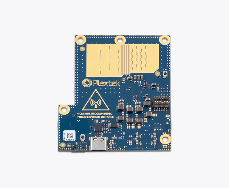
One significant advancement in imaging radar technology is the Frequency Modulated Continuous-Wave (FMCW) radar. FMCW radar offers advantages over pulsed-Doppler ranging techniques, particularly for short-range systems, where wideband systems can be realised to achieve fine resolution at millimetre-wave frequencies, making it well-suited for mobile applications and devices requiring continuous monitoring of surroundings. As a leading innovator in the field of electronics and communication technology, we developed a millimetre-wave radar demonstrator. This FMCW radar operates in the 60 GHz license-exempt band with state-of-the-art in electronically scanned radar systems.
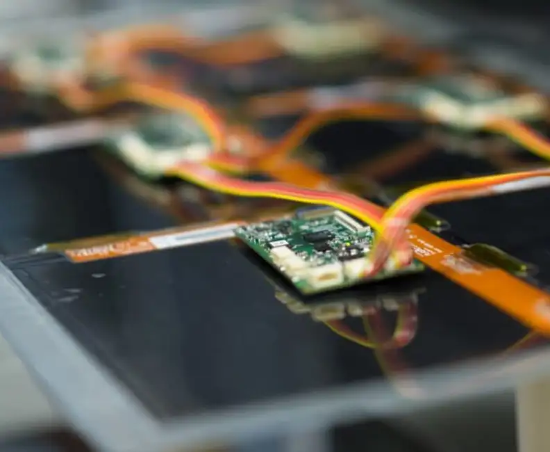
The components of an imaging radar system
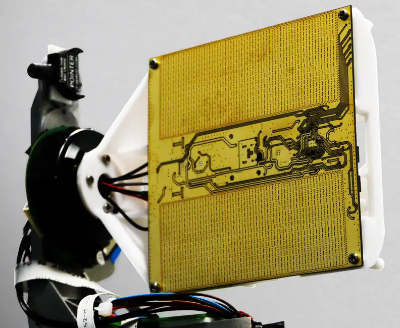
The heart of our imaging radar system lies in its clever architectural design, comprising four main components: a computer, a digitiser, a radio frequency (RF) front-end, and a waveguide horn antenna. The RF front-end is responsible for generating the millimetre-wave signals transmitted by the antenna and for demodulating the received signals. The digitiser, in turn, converts the analogue signals into their digital counterparts, making them suitable for computer processing. The antenna steers its main lobe as the frequency of the transmitted waveform changes. This setup allows the radar to swiftly scan its field-of-view without mechanical movement, relying instead on electronic scanning facilitated by changing the frequency of the transmitted waveforms.

Imaging radar: RRI and raw data
In the world of imaging radar, the Ramp Repetition Interval (RRI) (equivalent to the pulse repetition frequency in pulsed radar systems) is a critical concept. The RRI refers to the period during which the FMCW radar’s transmit frequency is modulated. In FMCW ranging techniques, this is typically done by transmitting a linear chirp that incrementally rises at a prescribed rate (up-ramp) before being quickly reset (down-ramp) to its starting frequency. This modulation pattern is pivotal for defining the radar parameters such as range and Doppler resolution, frame rate, instrumented range, and mitigating against aliasing effects. The digitiser captures samples across several RRIs, forming a ‘frame’ of raw data that encodes the reflections from objects at different distances and angles.
Processing radar data: from raw echoes to clear images
The journey from raw radar data to a comprehensible image is a complex process involving several stages of signal processing. Initially, the raw, time-domain signal is transformed into its frequency-domain representation. This step is essential for identifying the unique ‘tones’ corresponding to different reflection distances in the captured radar signals. Subsequent processing stages focus on extracting useful information from the frequency-domain data, discarding irrelevant parts, and constructing visual representations that closely resemble the observed scene.
Visualisation and interpretation
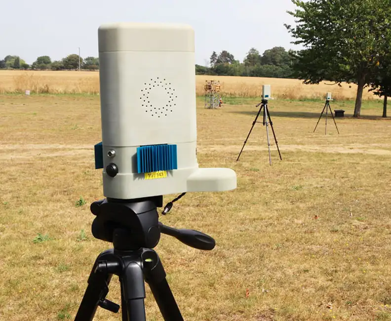
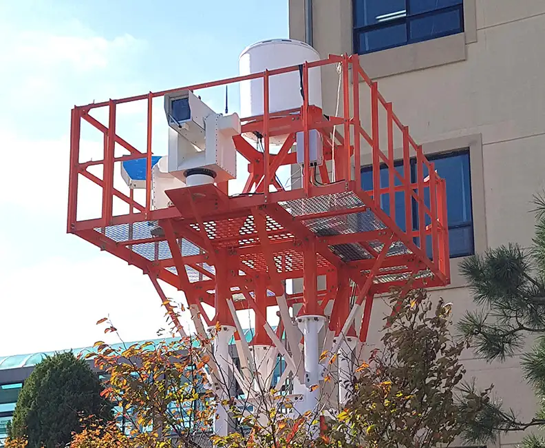
Many modern radar systems are used for integration into automated systems, such as the monitoring and detection of drones, vehicles, and pedestrians. In these contexts, a radar provides a powerful sensor, though the value often lies not in the visual representation of data but in the functional application of the information gathered. Whilst visualisations serve as a bridge, translating the abstract radar data into plots for the users or developers—thereby building trust in the system or aiding in troubleshooting—many users look beyond these images. For instance, our Ubiquitous Radar (PLX-U16) offers a range of visualisations; yet the core demand from users is for succinct detection reports that can trigger immediate actions in other systems, such as directing a camera towards a detected object. The visualisation is not an end but a means to a broader capability: the practical, responsive action based on data interpretation.
Please accept cookies in order to enable video functionality.
This video provides an example radar output, where a single visualisation is shown alongside the feed from a co-located video camera.
Challenges and future directions
Even with big improvements in radar technology and how we handle radar data, there are still some tough challenges. One major issue is dealing with the huge amount of data that advanced radar systems create. This requires powerful computers and sophisticated software to process all that information quickly. Another challenge is in interpreting radar data in complex scenarios. For example, a radar can be used to detect drones, but it could be confused by birds, vehicles, and other moving objects. Here, AI (Artificial Intelligence) comes in handy. It can help figure out what exactly the radar has detected, for example telling the difference between a bird and a drone. By teaching AI to identify these differences, radar systems become much more useful and easier to work with.
The future of imaging radar technology promises further advancements in processing speed and resolution. With continued innovation, imaging radar systems will play an increasingly prominent role in shaping the technological landscape, driving advancements in autonomous systems, environmental monitoring, and beyond.
Conclusion & further reading
Through the lens of our advanced millimetre-wave radar demonstrator, the guide illuminates the intricate processes involved in transforming raw radar echoes into detailed images of the world around us. As imaging radar technology continues to evolve, mastering the art of radar data processing will remain a key skill for engineers and developers working at the forefront of technological innovation.
For a full exploration, the guide “A Programmer’s Introduction to Processing Imaging Radar Data”, by Matthew Roberts, provides an invaluable resource for understanding the nuances of imaging radar data processing.


Got a project in mind?
Projects
View All
Machine Learning for Rapid Propagation Assessment
Developing a groundbreaking ML model for swift and efficient coverage prediction in complex urban environments, enabling rapid optimisation of transmitter locations on standard computing hardware.
Read More

Cost-Effective Improvement in mmWave Intensity
Enhancing the mmWave antenna design for Remedee Labs, significantly boosting RF radiation efficiency and cost-effectiveness in non-pharmaceutical chronic pain treatment.
Read More

Game-Changing Radar for the CLEAR Mission
Developing vital radar technology for the CLEAR mission, advancing space debris removal techniques to safeguard operational satellites and spacecraft.
Read More
Future Sensing: Improving Mobile Ad-hoc Networks
Leading a transformative four-year research initiative to improve mobile ad-hoc networks through advanced directional antenna systems and cross-layer processing, significantly enhancing military communication capabilities.
Read More
Millimetre-Wave Radar System
Expertly engineering a compact, high-performance 60 GHz millimetre-wave radar system using innovative Substrate Integrated Waveguide technology, achieving significant advancements in target detection up to 100 metres.
Read More
Communicating Across Surfaces
Using innovative expertise in metamaterials to facilitate the development of advanced surfaces, improving RF communication efficiency through pioneering surface wave technology for superior antenna design and wireless connectivity.
Read More

Armour Integrity Monitoring System (AIMS)
Innovating a new Armour Integrity Monitoring System (AIMS) for the UK MoD, delivering a low SWaP-C solution that dramatically streamlines logistics and enhances protection through in-field armour integrity checks.
Read More
mmWave Radar for Foreign Object Debris Detection
Collaborating with WaveTech to develop an advanced mmWave radar system, enabling the rapid and automated detection of foreign object debris on runways, enhancing safety and operational efficiency at a South Korean airport.
Read More

Spinbrush: From Insights to Strategy to Design
Discover how we enabled Spinbrush to leverage consumer insights to innovate and excel in the competitive powered toothbrush market with our strategic approach.
Read More

Energenie Smart Home Controller
Redesigning the Energenie Smart Home Controller interface to introduce low-power radio technology, enhancing device functionality for centralised home heating control, and launching nationwide.
Read More

Developing Automated Manufacturing Systems
Delivering a pioneering predictive maintenance solution for a global healthcare product company, utilising miniature battery-powered sensor systems to optimise automated production lines and significantly reduce costly downtimes.
Read More

Surveillance Radar for Comprehensive Threat Detection
Advancing a perimeter surveillance solution with long-range detection and low false-alarm rates, using state-of-the-art Passive Electronically Scanned Array technology for robust and maintenance-free operation in a range of demanding environments.
Read More
Downloads
View All Downloads- PLX-T60 Configurable mmWave Radar Module
- PLX-U16 Ubiquitous Radar
- Configurable IOT Framework
- MISPEC
- Cost Effective mmWave Radar Devices
- Antenna Design Services
- Plextek Drone Sensor Solutions Persistent Situational Awareness for UAV & Counter UAV
- mmWave Sense & Avoid Radar for UAVs
- Exceptional technology to positive impact your marine operations
- Infrastructure Monitoring
Technical Papers
View All
mmWave Imaging Radar
Camera systems are in widespread use as sensors that provide information about the surrounding environment. But this can struggle with image interpretation in complex scenarios. In contrast, mmWave radar technology offers a more straightforward view of the geometry and motion of objects, making it valuable for applications like autonomous vehicles, where radar aids in mapping surroundings and detecting obstacles. Radar’s ability to provide direct 3D location data and motion detection through Doppler effects is advantageous, though traditionally expensive and bulky. Advances in SiGe device integration are producing more compact and cost-effective radar solutions. Plextek aims to develop mm-wave radar prototypes that balance cost, size, weight, power, and real-time data processing for diverse applications, including autonomous vehicles, human-computer interfaces, transport systems, and building security.
Low Cost Millimeter Wave Radio frequency Sensors
This paper presents a range of novel low-cost millimeter-wave radio-frequency sensors that have been developed using the latest advances in commercially available electronic chip-sets. The recent emergence of low-cost, single chip silicon germanium transceiver modules combined with license exempt usage bands is creating a new area in which sensors can be developed. Three example systems using this technology are discussed, including: gas spectroscopy at stand off distances, non-invasive dielectric material characterization and high performance micro radar.
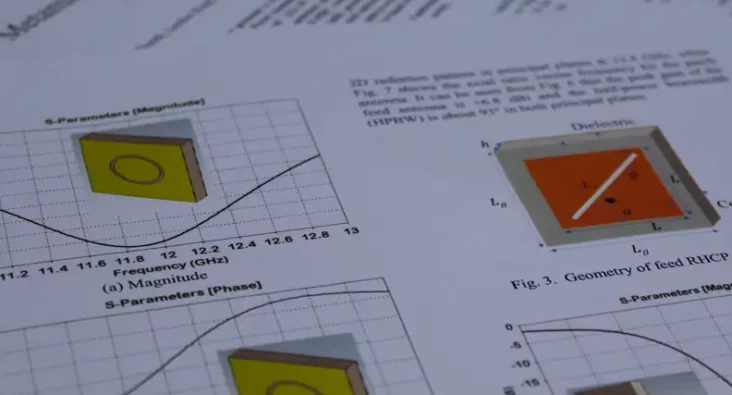
Metamaterial-Based Ku-Band Flat-Panel High-Grain
This technical paper by Dr. Rabbani and his team presents research on metamaterial-based, high-gain, flat-panel antennas for Ku-band satellite communications. The study focuses on leveraging the unique electromagnetic properties of metamaterials to enhance the performance of flat-panel antenna designs, aiming for compact structures with high gain and efficiency. The research outlines the design methodology involving multi-layer metasurfaces and leaky-wave antennas to achieve a compact antenna system with a realised gain greater than +20 dBi and an operational bandwidth of 200 MHz. Simulations results confirm the antenna's high efficiency and performance within the specified Ku-band frequency range. Significant findings include the antenna's potential for application in low-cost satellite communication systems and its capabilities for THz spectrum operations through design modifications. The paper provides a detailed technical roadmap of the design process, supported by diagrams, simulation results, and references to prior work in the field. This paper contributes to the advancement of antenna technology and metamaterial applications in satellite communications, offering valuable insights for researchers and professionals in telecommunications.
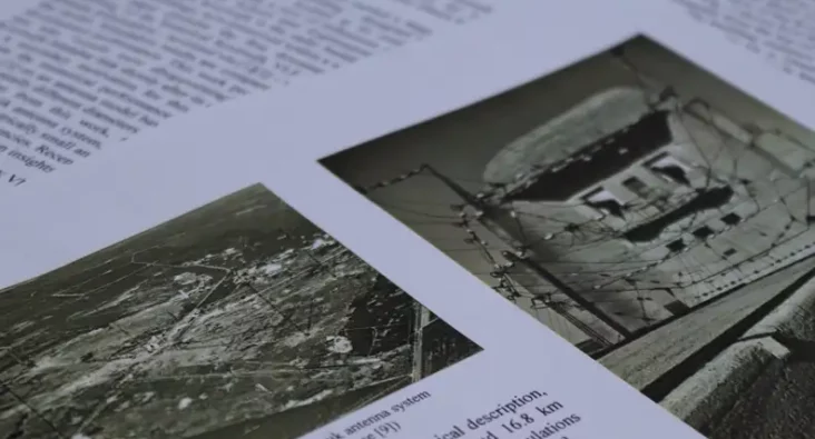
The Kootwijk VLF Antenna: A Numerical Model
A comprehensive analysis of the historical Kootwijk VLF (Very Low Frequency, which covers 3-30 kHz) antenna, including the development of a numerical model to gain insight into its operation. The Kootwijk VLF antenna played a significant role in long-range communication during the early 20th century. The paper addresses the challenge of accurately modelling this electrically small antenna due to limited historical technical information and its complex design. The main goal is to understand if the antenna’s radiation efficiency might explain why “results were disappointing” for the Kootwijk to Malabar (Indonesia) communications link. Through simulations and comparisons with historical records, the numerical model reveals that the Kootwijk VLF antenna had a low radiation efficiency – about 8.9% – for such a long-distance link. This work discusses additional loss mechanisms in the antenna system that might not have been considered previously, including increased transmission-line losses as a result of impedance mismatch, wires having a lower effective conductivity than copper and inductor quality factors being lower than expected. The study provides insights into key antenna parameters, such as the radiation pattern, the antenna’s quality factor, half-power bandwidth and effective height, as well as the radiated power level and the power lost through dissipation. This research presents the first documented numerical analysis of the Kootwijk VLF antenna and contributes to a better understanding of its historical performance. While the focus has been at VLF, this work can aid future modelling efforts for electrically small antennas at other frequency bands.
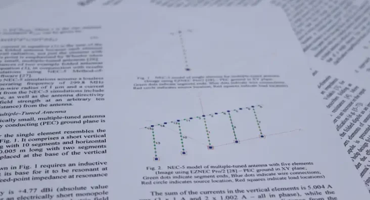
On the Radiation Resistance of Folded Antennas
This technical paper highlights the ambiguity in the antenna technical literature regarding the radiation resistance of folded antennas, such as the half-wave folded dipole (or quarter-wave folded monopole), electrically small self-resonant folded antennas and multiple-tuned antennas. The feed-point impedance of a folded antenna is increased over that of a single-element antenna but does this increase equate to an increase in the antenna’s radiation resistance or does the radiation resistance remain effectively the same and the increase in feed-point impedance is due to transformer action? Through theoretical analysis and numerical simulations, this study shows that the radiation resistance of a folded antenna is effectively the same as its single-element counterpart. This technical paper serves as an important point of clarification in the field of folded antennas. It also showcases Plextek's expertise in antenna theory and technologies. Practitioners in the antenna design field will find valuable information in this paper, contributing to a deeper understanding of folded antennas.

Analysis of Chilton Ionosonde Critical Frequency Measurements During Solar Cycle 23 in the Context of Midlatitude HF NVIS Frequency Predictions
This paper presents a comparison of Chilton ionosonde critical frequency measurements against vertical-incidence HF propagation predictions using ASAPS (Advanced Stand Alone Prediction System) and VOACAP (Voice of America Coverage Analysis Program). This analysis covers the time period from 1996 to 2010 (thereby covering solar cycle 23) and was carried out in the context of UK-centric near-vertical incidence skywave (NVIS) frequency predictions. Measured and predicted monthly median frequencies are compared, as are the upper and lower decile frequencies (10% and 90% respectively). The ASAPS basic MUF predictions generally agree with fxI (in lieu of fxF2) measurements, whereas those for VOACAP appear to be conservative for the Chilton ionosonde, particularly around solar maximum. Below ~4 MHz during winter nights around solar minimum, both ASAPS and VOACAP MUF predictions tend towards foF2, which is contrary to their underlying theory and requires further investigation. While VOACAP has greater errors at solar maximum, those for ASAPS increase at low or negative T-index values. Finally, VOACAP errors might be large when T-SSN exceeds ~15.
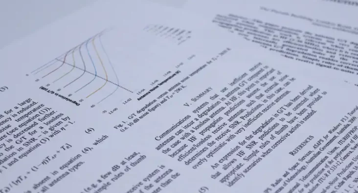
Antenna GT Degradation with Inefficient Receive Antenna at HF
This paper presents the antenna G/T degradation incurred when communications systems use very inefficient receive antennas. This work is relevant when considering propagation predictions at HF (2-30 MHz), where it is commonly assumed that antennas are efficient/lossless and external noise dominates over internally generated noise at the receiver. Knowledge of the antenna G/T degradation enables correction of potentially optimistic HF predictions. Simple rules of-thumb are provided to identify scenarios when receive signal-to-noise ratios might be degraded.
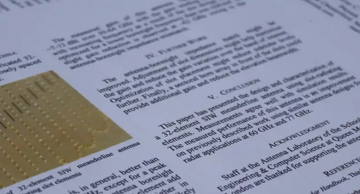
Frequency-Scanning Substrate-Integrated-Waveguide Meanderline Antenna for Radar Applications at 60GHz
This paper describes the design and characterization of a frequency-scanning meanderline antenna for operation at 60 GHz. The design incorporates SIW techniques and slot radiating elements. The amplitude profile across the antenna aperture has been weighted to reduce sidelobe levels, which makes the design attractive for radar applications. Measured performance agrees with simulations, and the achieved beam profile and sidelobe levels are better than previously documented frequency-scanning designs at V and W bands.
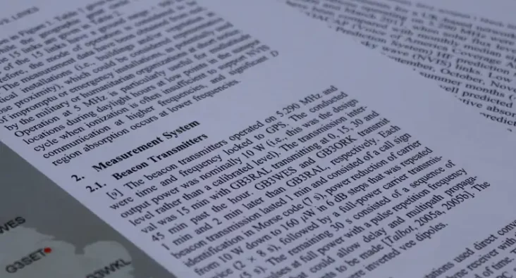
Comparison of Propagation Predictions and measurements for midlatitude High Frequency
Signal power measurements for a UK-based network of three beacon transmitters and five receiving stations operating on 5.290 MHz were taken over a 23 month period between May 2009 and March 2011, when solar flux levels were low. The median signal levels have been compared with monthly median signal level predictions generated using VOACAP (Voice of America Coverage Analysis Program) and ASAPS (Advanced Stand Alone Prediction System) HF prediction software with the emphasis on the near-vertical incidence sky wave (NVIS) links. Low RMS differences between measurements and predictions for September, October, November, and also March were observed. However, during the spring and summer months (April to August), greater RMS differences were observed that were not well predicted by VOACAP and ASAPS and are attributed to sporadic E and, possibly, deviative absorption influences. Similarly,the measurements showed greater attenuation than was predicted for December, January, and February, consistent with the anomalously high absorption associated with the “winter anomaly.” The summer RMS differences were generally lower for VOACAP than for ASAPS. Conversely, those for ASAPS were lower during the winter for the NVIS links considered in this analysis at the recent low point of the solar cycle. It remains to be seen whether or not these trends in predicted and measured signal levels on 5.290 MHz continue to be observed through the complete solar cycle.
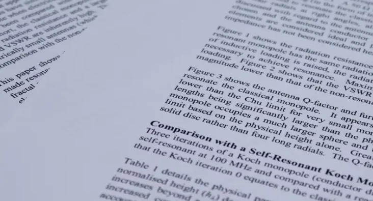
On using the classical monopole for comparison with other electrically small self-resonant monopole antennas of equal height
This paper shows that the Q-factor and VSWR of a monopole are significantly lowered when made resonant by reactive loading (as is used in practice). Comparison with a self-resonant Koch fractal monopole of equal height gives similar values of VSWR and Q-factor. Thus, the various electrically small monopoles (self-resonant and reactively loaded) offer comparable performance when ideal and lossless. However, in selecting the optimum design, conductor losses and mechanical construction at the frequency of interest must be considered. In essence, a trade-off is necessary to obtain an efficient, electrically small antenna suitable for the application in hand.

A Ku-Band, Low Sidelobe Waveguide Array Employing Radiating T Junctions
The design of a 16-element waveguide array employing radiating T-junctions that operates in the Ku band is described. Amplitude weighting results in low elevation sidelobe levels, while impedance matching provides a satisfactory VSWR, that are both achieved over a wide bandwidth (15.7-17.2 GHz). Simulation and measurement results, that agree very well, are presented. The design forms part of a 16 x 40 element waveguide array that achieves high gain and narrow beamwidths for use in an electronic-scanning radar system.
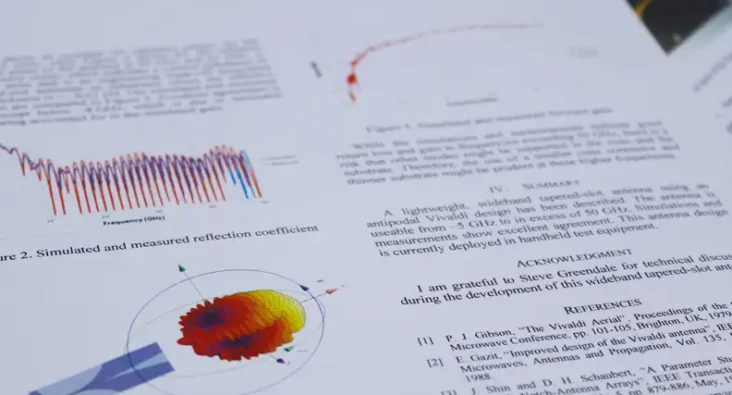
A Wideband, 5-50+GHz Tapered-Slot Antenna For Use in Handheld Test Equipment
A lightweight, wideband tapered-slot antenna that uses an antipodal Vivaldi design and provides useable gain from ~5 GHz to in excess of 50 GHz is described. Simulations and measurements are presented that show excellent agreement. This antenna design is currently deployed in handheld test equipment.